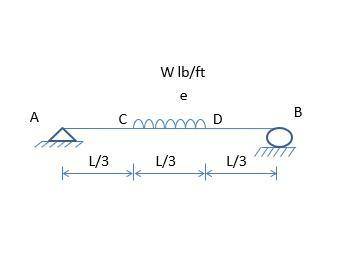
Draw the Shearing Force and Bending Moment diagram with its derivation.
...

Engineering, 20.12.2021 14:00 minie66
Draw the Shearing Force and Bending Moment diagram with its derivation.


Answers: 2


Another question on Engineering

Engineering, 03.07.2019 19:30
When using the ohmmeter function of a digital multimeter, the leads are placed in what position relative to the component being tested? a. parallel b. control c. series d. line
Answers: 3

Engineering, 04.07.2019 18:10
The flow rate of air through a through a pipe is 0.02 m5/s. a pitot static tube is placed in the flow. the radius of the pitot static tube is 1 mm. assuming the flow to be steady and the air to be at 300k, calculate the difference in total and static pressure if the diameter of the pipe is: (a) d 0.1 m d 0.05 m (c) d 0.01 m
Answers: 2

Engineering, 04.07.2019 18:20
A2-m rigid tank initially contains saturated water vapor at 100 kpa. the tank is connected to a supply line through a valve. steam is flowing in the supply line at 600 kpa and 300 c. the valve is opened, and steam is allowed to enter the tank until the pressure in the tank reaches the line pressure, at which point the valve is closed. a thermometer placed in the tank indicates that the temperature at the final state is 200°c. determine (a) the mass of steam that has entered the tank (b) the amount of heat transfer.
Answers: 3

Engineering, 04.07.2019 19:10
Arigid tank contains 10 kg of air at 137 kpa (abs) and 21°c. more air is added to the tank until the pressure and temperature rise to 242 kpa (abs) and 32°c, respectively. determine the amount of air added to the tank. [r-0.287 kj/kg k]
Answers: 3
You know the right answer?
Questions

Mathematics, 30.10.2019 21:31

Biology, 30.10.2019 21:31

History, 30.10.2019 21:31

Health, 30.10.2019 21:31

Mathematics, 30.10.2019 21:31

Mathematics, 30.10.2019 21:31

Computers and Technology, 30.10.2019 21:31


English, 30.10.2019 21:31

Mathematics, 30.10.2019 21:31

Social Studies, 30.10.2019 21:31

Mathematics, 30.10.2019 21:31

History, 30.10.2019 21:31

Health, 30.10.2019 21:31

Biology, 30.10.2019 21:31


