Engineering, 14.06.2021 06:50 deena7
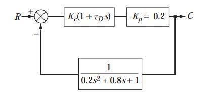
Plot the root locus diagram for the Plot the root locus diagram for the system shown in . We may consider this system to consist of a process having negligible lag; an underdamped, second-order measuring element; and a PD controller. This system may approximate the control of flow rate, in which case the block labeled K p would represent a valve having no dynamic lag. The feedback element would represent a flow measuring device, such as a mercury manometer placed across an orifice plate. Mercury manometers are known to have underdamped, second-order dynamics. Plot the diagram for t D 13 We may consider this system to consist of a process having negligible lag; an underdamped, second-order measuring element; and a PD controller. This system may approximate the control of flow rate, in which case the block labeled K p would represent a valve having no dynamic lag. The feedback element would represent a flow measuring device, such as a mercury manometer placed across an orifice plate. Mercury manometers are known to have underdamped, second-order dynamics. Plot the diagram for t D 13 .
Answers: 3


Another question on Engineering
Engineering, 03.07.2019 14:10
Explain the difference laminar and turbulent flow. explain it with the shear stress and the velocity profiles.
Answers: 1
Engineering, 04.07.2019 18:10
What difference(s) did you notice using a pneumatic circuit over hydraulic circuit.explain why the pneumatic piston stumbles when it hits an obstacle.
Answers: 2
Engineering, 04.07.2019 18:10
Afour cylinder four-stroke in-line engine has a stroke of 160mm, connecting rod length of 150mm, a reciprocating mass of 3kg and its firing order is 1-3-4-2. the spacing between cylinders is 100mm. i. show that the engine is in balance with regard to the primary inertia forces and primary 3. a and secondary inertia couples. li determine the out of balance secondary inertia force ii. propose ways of balancing this out of balance force and discuss the challenges that will arise
Answers: 3
Engineering, 04.07.2019 18:10
Slip occurs via two partial dislocations because of (a) the shorter path of the partial dislocation lines; (b) the lower energy state through partial dislocations; (c) the charge balance.
Answers: 1
You know the right answer?
Plot the root locus diagram for the Plot the root locus diagram for the system shown in . We may con...
Questions
Mathematics, 10.09.2019 07:10


Mathematics, 10.09.2019 07:10
Mathematics, 10.09.2019 07:10
Mathematics, 10.09.2019 07:10

History, 10.09.2019 07:10
English, 10.09.2019 07:10
Mathematics, 10.09.2019 07:10

Biology, 10.09.2019 07:10
Mathematics, 10.09.2019 07:10
History, 10.09.2019 07:10
Biology, 10.09.2019 07:10